Monday, October 15, 2012

Transonic Clouds Forming

After watching the supersonic flights on this YouTube video , I realized that it is possible to see condensation clouds forming right before the tip of the aircraft/rocket. I then asked myself where have I seen this before? A quick visit to my SR 700 flight and I was able to see this phenomenon in my own flight!

 
 At around 0:25 seconds in the video the cloud becomes visible for a short time then disappears as it goes beyond the sound barrier (i think).

Sunday, September 9, 2012

SR 700 Flight


Sugar Rocket J700 flight

I am in awe of the sound!


Sunday, September 2, 2012

SR 700 Rocket Build


Materials used:
  • PVC drain pipe
  • PVC pressure pipe and fittings
  • 3/16 ply wood
  • Car body filler
  • Hot melt glue
  • Epoxy
  • Aluminum tape
  • Galvanized screws
Tools:
  • Hot melt Glue gun
  • Hacksaw
  • Dremel 4000
  • Grinder
  • Screw driver,
  • Etc, lol 
Below is a slideshow with pics of the build process

Saturday, July 21, 2012

Importance of the test stand - J680 Test (Failure)

This was the first test of this motor design. Motor is designed to be operating at a maximum of 612 PSI, a pressure which my other motors have no problem with. In this test, however, the nozzle blew out. Without the pressure gauge and video I would assume that the concrete nozzle was not sufficient to hold the expected 612 PSI of this motor. Conveniently, I had a pressure gauge connected to the motor which was able to show in the video that the nozzle was not the cause of the failure. May not be the best test stand in the world but it surely beats nothing!


The gauge has a maximum reading of 1,000 PSI with a number at every 200 psi graduation. If you watch the video you will see where the gauge passes 1,000 PSI!! The nozzle held well up to 1,000 psi so it surely wasn't the cause of the failure.

I'm now thinking that the grains were not inhibited properly. I used 3 layers of posterboard paper as inhibitor. Comments are welcomed.

Update:

It was explained to me by a senior sugpro member that my high pressure may not be just a problem with inhibition, but rather the fact that I'm using sucrose and dextrose and not purely dextrose as the reducer. My motor design was based on the assumption of dextrose fuel, but the sucrose+dextrose mix may have caused the motor to behave more like a sucrose only mixture, or at least an average of the two. This means higher pressures than expected.


Video and snapshots follows:

0 PSI

80 PSI

420 PSI

800 PSI

1,000 PSI

Failure

Motor specs


Sunday, July 1, 2012

Dual deploy from a single compartment? - Tether release it!


If you are flying anything over an I-class motor, then you are probably already using dual deployment in your recovery system. The problem with dual deployment is that they (usually) use 2 chambers for each parachute - one for the drogue, another for the main.

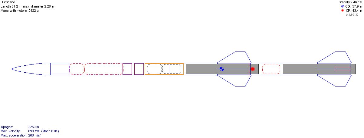
That was a problem for me with the ‘Hurricane’ rocket build. I didn’t have the space for two parachute chambers, and adding a second one simulated at a much lower altitude. What was the solution? A tether release dual deployment setup.

A tether release setup utilizes one chamber for both drogue and main parachute. When the rocket reaches apogee, everything is ejected (nose, drogue, main chute). The main is however restrained and not allowed to inflate until the appropriate altitude is met during descent. Once the rocket reaches the correct altitude, the charge for the main parachute cuts the retaining cord and allows the chute to inflate.

Some folks have drilled bullet casings in their setup. They drill the casings right through, running the retaining cord (fish line) through it, fill the shell up with black powder, and then seal it. The basic idea is to have the charge cut a string that was holding your main chute from inflating.

In the ‘Hurricane’, i basically utilized a drinking straw as bullet casings is illegal to use in my country. The straw is cut to about an inch and pierced right through the middle with a hot needle sewing needle.  A fishing line is then fed through the holes and an igniter placed on the inside of the straw. The straw is then filled with BP and sealed with hot glue or crazy glue/superglue.


Next, I rolled the chute like normal – keeping the shroud lines on the inside. The rolled parachute is then placed in computer paper for protection – this is where some guys use nomex to make what they call a burrito for the chute. The fish line with the pyro-straw wraps around the chute really tight and tied into a knot and will hold until the pyrostraw is fired. For extra protection, a piece of aluminum tape is placed under the straw so that it doesn’t burn through the paper and burn the chute. A small square of poster board can be used here as well.


The most important part of this setup is the tether. The tether was simply a nylon cord where one end connects to the fishing line, and the other connects to the shock cord. The purpose of this is to keep the ejection forces off the parachute itself and prevents it from breaking the lead wire. I made a small video ato demonstrate what i did.


And here is a video 

Monday, June 25, 2012

Cat 5 Hurricane Build Progress

Booster and Sustainer fin outline

Angle grinder. Cuts everything: Fins, slots, tubes.


Booster and sustainer fin cans


Just barely assembled. Not straight as yet :)

I may reduce the size of the booster section. Just haven't figured out the deployment system for that part as yet


Tuesday, May 22, 2012

Second Stage Ignition Device

Second Stage Ignition Device- Click to enlarge


How will it work?

The main components in this design are the burnout detector, the SCR component, and the 555 timer circuit.

When the rocket takes off under the power of the 1st stage, everything is moving at the same velocity –including the steel ball. Once the 1st stage motor burns out, it causes the rocket to stop accelerating and due to air resistance the rocket begins to slow. However, the steel ball does not slow down as quickly as the rocket because there is no air resistance to affect it. So, the steel ball travels forward (up) and closes the switch. It's like holding the brake while going fast - u travel forward. In this case the air resistance is the brake on the rocket's body.

That part of the gadget was derived from Alberto/Dan Polino's Apogee detector.

The SCR now comes into play. The SCR is a semiconductor that can be configured as a switch. What makes this switch so special is that once it is turned on, the SCR will remain on even if the switch (steel ball switch) becomes open. This is crucial in triggering the timer and maintaining that voltage to the timer

The timer’s responsibility is to delay the ignition by (X) amount of seconds. This is needed to take advantage of a coasting period to attain maximal altitude before igniting the second stage. This second stage must be ignited before the rocket begins to slow too much. And that is basically how this contraption works - in theory

Sunday, May 20, 2012

2 Stage Sugar Rocket - Category 5 Hurricane

A two-stage rocket derived from the 'Hurricane' is currently being designed. This rocket, called the 'Category 5', features two I-350 motors that should propel the rocket well over 7500 ft. Clearance will be sought from the CAA before this is launched.

Here is the current design.


You may be wondering why 2 similar motors are being used instead of the traditional big booster -> smaller sustainer setup. The reason lies in the fact that the biggest motor this tube can take is an I-350 sugar PVC and based on simulation in Open Rocket the motor seems to be strong enough to lift the extra weight of the upper stage with ease.

Material / Components List (so far) - sans motors

  • 1 and 1/2 blueprint tube or a full length fabric tube
  • 2 small umbrellas 
  • 1 large umbrella
  • 2x 1.25 PVC end caps for bulkhead and ejection plunger
  • Nosecone made from body filler
  • 1.5 inch PVC drain pipe for couplers and nosecone neck
  • Solitex or MDF wood based Clipboard  - for fins
  • Screws? I forgot the size they are but I know i need 8 1/8 Self tapping screws
  • 2x 1/4 inch machine screw for launch guides - the head of these are big enough to function as buttons
...more to come

Monday, May 7, 2012

Thunderbolt Rocket - Launch


Here it is my friends:


The motor was actually nearer to an I-350 spec, not an I-400. All in all the flight was successful notwithstanding the main chute releasing a little earlier than planned. I’m not sure how but I’m guessing the nosecone was shaken off the tube and eventually pull the main chute out. This “thunderbolt rocket” is heavier than the “hurricane“ so the apogee as lower.

A remake of the Hurricane will be flown soon, painted in pink (for that special lady who will be present)
Can't wait!

Tuesday, April 10, 2012

i-500 Hurricane Rocket - First Flight

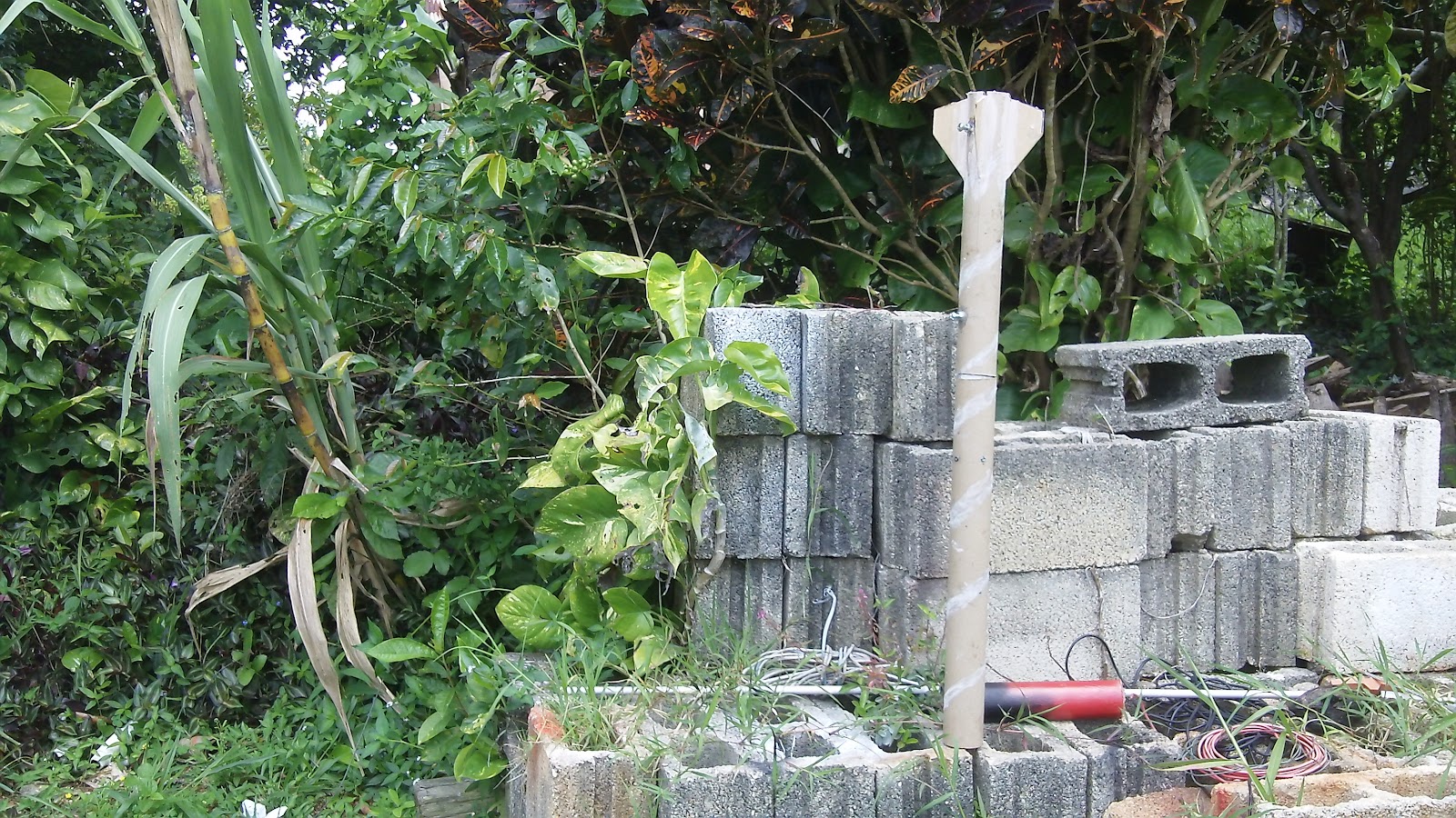
A picture is worth a thousand words...

Here is a complete video of the launch, with onboard video.


Basically, the motor had a blowby that created a "second nozzle" on the inside of the rocket. It pressurized the inside of the tube removing the lower part of the tube and two fins two fins with it. Only got 400 ft altitude.
Stay tuned for the second attempt.

Sunday, April 1, 2012

Building the "Hurricane" rocket.

Always wanted to make an altimeter supported rocket. Well, here it is: the hurricane.


Wood sealer applied, makes everything sandable

Wood Sealer added. Sanding is next

Not yet sanded
 
Flat black

Drying the paint

Smooth Nosecone with gloss red


Finally


Video:

Friday, March 30, 2012

Simple way of testing altimeter

This is a common way of testing altimeters without flying it. Saw it on the Adeptrocketry website.


Components:
Baby juice bottle (small as possible)
10ml syringe
Altmeter and wires

I simple punchtured the juice bottle, insert the syringe and hot glue it  so it is air tight. Epoxy could be used.
Holes were created in the cork to allow wires to come through. Again, hot glue or epoxied in.

The syringe allows a change in pressure on altimeter, it triggers the apogee trigger when the pressure stops falling inside the bottle.

Works for me!

Sunday, February 5, 2012

Rocket Recovery: GPS devices

Secured in the nosecone, this is the GPS device that will help locate the bird after it has landed. It is a TK-102 GPS clone. You simply call the device and it returns the coordinates to your phone. You can then look that up on google maps on your ipad or laptop. It requires having a GSM SIM card inside. 

It weights only 58 grams and is small enough for H class rockets. 


Edit:

This only works if you have cellphone coverage. If you will be launching in the desert where there is no coverage then you will need one of these $400 devices

Knowing the Wind Speed: GO Launch or NO-GO Launch

It may not be crucially important to some to know how fast the wind is blowing right before launch, but for me it is very important as I dont have alot of recovery area to play with.

I stumbled upon this video that shows how to make an anemometer that can measure (roughly) windspeeds.

IF you have 25 bucks to spare you could simply get one of these:

Saturday, January 28, 2012

Test of Bridgeless Igniters

I wanted the most reliable, low amperage igniters for my deployment system. My system employs a 9V battery through a NE555 timer that delays for 12.5 seconds.

I wanted to see if my dipped bridgeless igniters were capable of consistent and reliable results.

the dipped igniters are not the sensitive type that other pyros make. These were dipped into a mixture of graphite, kno3, and sulfur + lacquer and acetone for the liquid component.

According to this test, the only thing consistent was their inconsistency!

I noticed that they smoked for 1-3 seconds before they send a flame out and ignite the pyrogen. That is not good enough for me, maybe for launch but not for deployment.

I'd rather use the 40 gauge nichrome that gives me instant ignition every single time.

Friday, January 27, 2012

Making Nosecone [ From Body Filler ]

Video below shows another nosecone I made from plastering car body filler over a wooden plug. A condom (yes, condom)  was placed over the wooden plug so that it would not stick to it and could be released quite easily. I used two application of body filler to get it where it is in this video. I sanded out the pits and bumps between each layer.


I will try and do a video that shows how to make a nosecone like this.

Here is the finished product next to an incomplete one:


Tuesday, January 24, 2012

Nichrome wire - With ejection timer Test

I just received 250ft of 40guage nichrome wire. Cost was 11 bucks from Jacobs Online.
The second photo shows how thin the wire is, look for a hair like object to in front of the coil.
This will be used in my deployment system.


First Tests:

My first 6 or so tests failed. The nichrome did not ignite the kno3/sucrose at all! In fact, it actually ignited it whenever it wasn't confined in the ignitor. I cannot explain why that was so. I tried it with BP and the result was similar. I could smell the sulphur but no ignition. I then went and get a newer 9V battery to do the test. I recorded the result below:


Sunday, January 15, 2012

Ejection Timer Test


Based on the design that was displayed in a previous post, this is the result.
I'm thinking 14 seconds is too long. Going to try and get a potentiometer to adjust timing.

EDIT:
I've since modified it to 12.5 seconds. Perfect!

Thursday, January 12, 2012

Ejection Timer Circuit

Below is the design for my prototype ejection timer. It uses an NE555 timer for the delay and an N channel MOSFET to do the switching. Powering this circuit is a 9v alkaline battery. The master switch is switched on right before launch. At that point the circuit is powered but the parachute delay is not yet triggered. The break-wire  will serve that purpose. It is this break-wire that will be broken during launch. This can be done by hooking something grounded to the launchpad and the exposed vreak-wire on the fuselage. As soon as the rocket leaves the pad the wire breaks and the countdown begins.

12 seconds deployment timer


Sunday, January 8, 2012

Using SRM, Free ENG Editor and OpenRocket

I created a page that shows how to design rockets from scratch Using SRM, Free ENG Editor and OpenRocket.

Constructing PVC Ejection Piston

Today I set out to create my PVC ejection piston. I've seen some online that required some sanding of couplings to get it to fit inside the cylinder and they also used an o-ring. They were also single use pistons.
I created this video below to document what I did today.

Material list:
- 8 inch length of 1" inch sch 40 pvc pipe.
- 8 inch
- Hot glue or clear silicone.
- 2 x1" inch PVC caps

  1. Cut a PVC of 1" sch 40 PV, 8 inches long. This will be the cylinder for the piston.
  2. I cut small ring (about 1/4 inch) from the piece that would become the cylinder.
  3. Sand and roughen up the ends of the 1/2 inch PVC.
  4. Use some WD-40 or cooking oil to lubricate the ring.
  5. Squeeze some hot glue or clear silicone inside the ring, just enough to fill the ring and very slightly overflow. This I expect will become the piston head.
  6. Insert piston arm into the glue. Use whatever means to make it stand 90 degrees upright.
  7. Let it dry.
    1. For the hot glue u can place it in the fridge to harden, but not before it sets.
    2. Clear silicone should take 12 hours to cure.
  8. Remove PVC ring. Give it a slight twist to help you.
  9. Bore a 1 inch PVC end cap just big enough to accommodate bridge wire / e-match / ignitor.
  10. Pull out excess wire wire, add some silicone to seal it off. 
  11. Add a spoonful of kno3/sugar.
  12. Cement end cap to cylinder
  13. Add some grease on the piston and insert piston into cylinder.
  14. Add  PVC cement on the cap and on the cylinder.
  15. Insert cap over piston rod and over the cylinder to seal the cylinder.
  16. Add 1/2 inch PVC cap over the free end of the piston rod.
*Clear Silicone can be used to form the piston plunger but it requires overnight curing. It is also weaker than the hot glue.
That's it for now

here is the video

Second edition,

the smoke is mostly from the back where the bridge wire is. It wasn't sealed permanently because I was testing different setup.

Update - Feb 11, 2012
Testing the piston with parachutes.

Saturday, January 7, 2012

Test of 9V Batteries and Bridge Wires.

Batteries vs Bridge Wires

So I finally got around to construct my Ejection Timer for my next project. This device will carry a 9V battery to power the circuit and burn the bridge wire that ignites the ejection charge. I though tit would be appropriate to test my battery with the bridge wire to see how fast it ignites the charge.

Below is an example of the steel wool I used in this test. I also tested 40awg nichrome wire
Panasonic Carbon-Zinc
To my surprise, the wire barely got heated with the power from these 9V carbon-zinc Panasonic batteries. At first I thought the battery was dead on arrival (or DOA), so I ordered another one of the same brand just to make sure. Unfortunately the result was the same.

My next bet was to try the nichrome bridge wire. I quickly constructed the ignitor and switch on the batteries, this time using both batteries in parallel for more amperage. They failed, terribly. The nichrome didn't even glow


Duracell Alkaline
At that point I start having doubts for this ejection system and considered abandoning the electronics. I made one last attempt and try a different brand and type of battery: Duracell / Alkaline.


I'm happy to announce that this battery burned the thick steel wool in an instant! Hope has been restored to my project and tomorrow I will begin soldering.

One thing I will be sure to do, is to have a test battery different from launch battery. The launch battery will be brand new and unused. I just cant risk launching a high powered rocket that fails the recovery.

Conclusion
Stick with Duracell or Energizer alkaline batteries, or better. My guess is that Carbon Zinc based batteries wont be able to deliver the current we need for ignition. Lithium based batteries probably have more punch, but that was not tested here.